Journey into fragment shaders - 2 - Masks
One of the most fundamental skills in shaders is the ability to create “masks”. With the ability to create masks you can create all sorts of shapes, color things how you like and specifically section off parts of your shader. A lot of shaders at their core contain some sort of mask in one way or another, by building up from these basic masks we can create amazing and complex shading effects and shapes!
What is a mask?
A mask in its most simplest form can be seen as a gray-scale image. In other applications this might be seen as the idea of “alphas”. Here are two examples of masks:
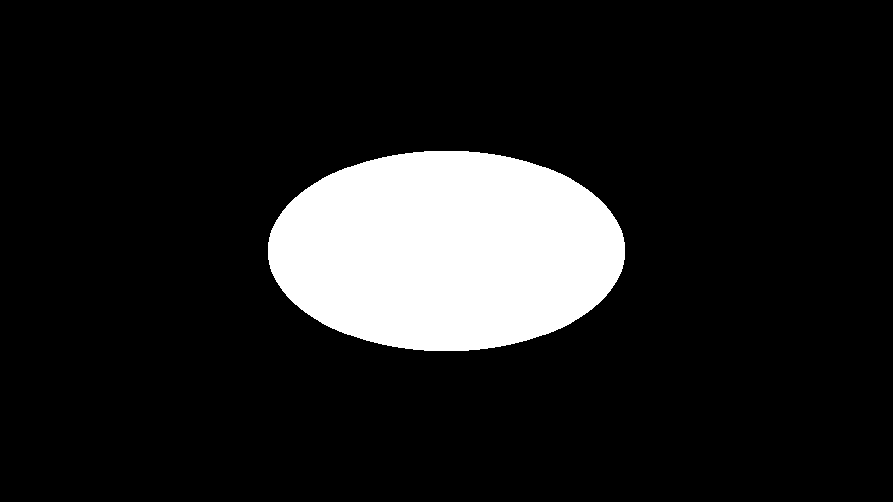
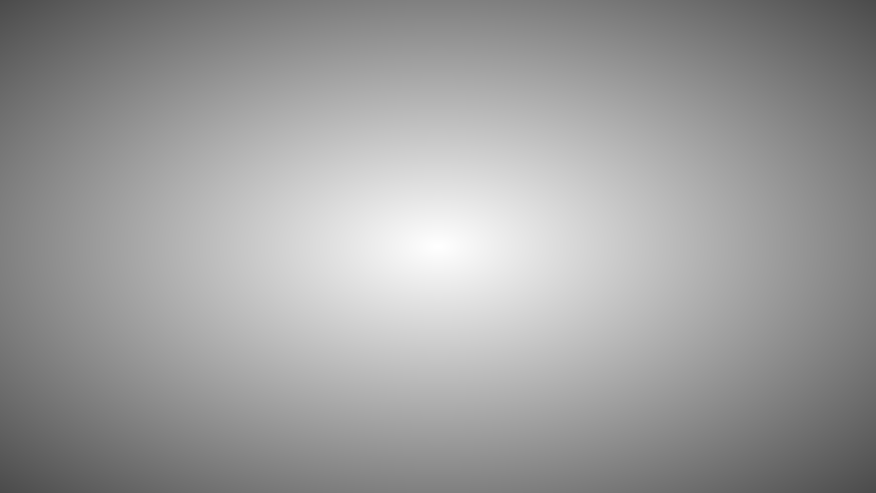
As you notice they’re nothing special, they’re just a gray-scale image which ranges from 0->1. We’re going to look at creating these types of masks, find out how they are made and how they work. We’re also going to see why masks are so important and the power they have from just a few simple shapes!
Signed distance fields
We’re going to look at creating the most basic mask to start off, the circle. We’re going to have to dip our toes a little bit into math here but it’s nothing too bad at least for now. One principle idea to build these masks is going to be the idea of “Signed Distance Fields” or a “Signed Distance Function”(SDF for short). Now this does look very intimidating but i’m going to break it down. In its simplest form, a SDF function returns the distance from two points. As our shader program runs the exact same program on every pixel of our object, we can calculate the distance from our current pixel to a fixed point which we know of, essentially creating a grid of distances to a specific point as shown below
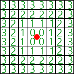
Now specifically I picked a circle to be the first mask to demonstrate this because essentially the image above is how we’ll create a circle mask! Lets start by breaking down a circle. If we go back to geometry in high school, we’ll remember that a circle has one key property in it which is it’s radius. The radius of a circle is the distance from the center of the circle to the rim of it. This radius is the same no matter where you draw your radius line as you can see below.
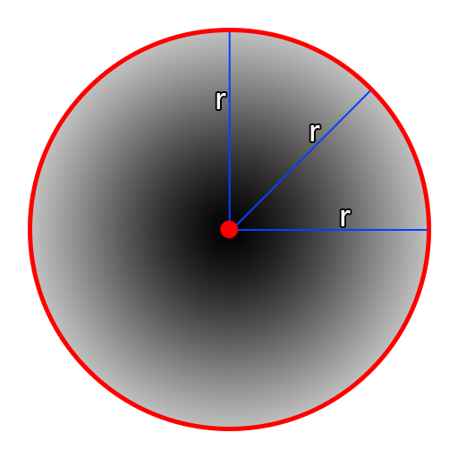
That means we only need to compute the distance from our current pixel to a point to create a basic circle! However how do we calculate distance?
Vectors and euclidean distance
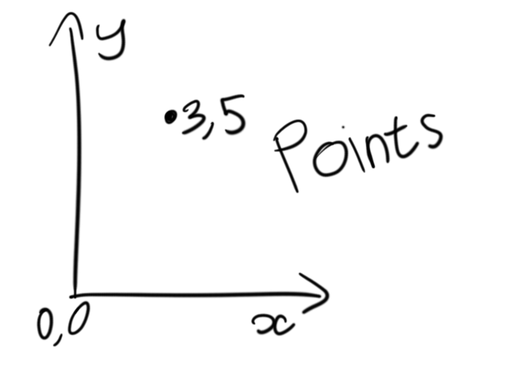
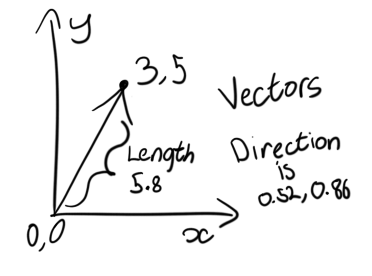
Vectors are very scary to some people however they have some very nice properties which we can use. The basics of a vector is that they have two main components, they have a direction component and a magnitude. Mostly in computer graphics people have been exposed to vectors as “points in space”, however these are not actually the case, because of the properties vectors have they are still directions with a magnitude. Typically in video games or “vectors as points” they can be visualized as a “direction and distance” from the world origin. Below shows the different properties of a point vs a vector and how to represent one of the other with the same values.
It’s important to break down the math of vectors and where these components come from. Understanding this will help quite a bit.
The main component we want to look at right now is known as the vector length, or the euclidean distance as it goes by other names. A lot of you might already know about this but never thought it has anything to do with vectors. We’re going to use something known as pythagoras theorem. A lot of you might of heard of this name quite a bit in trigonometry class. In it’s most basic explanation, it’s a simple formula used to calculate the length of any side of a right angle triangle given if you know two sides.
\[a^{2}+b^{2}=c^{2}\]The values \(a\) and \(b\) are the length of the two sides and \(c\) is the length of the hypotenuse (the longest side of the triangle). If we break our vector down to its most basic form, we can see how to calculate the “length”.
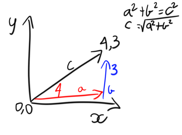
Each one of our vector components can be broken down into a single axis and represent a right angled triangle. Since our vector can be broken down into a triangle we can calculate pythagoras theorem to calculate the length length of our vector from the origin or in this case \(c\). In our case above our length can be calculated as: \(a^{2}+b^{2}=c^{2}\)
\[4^{2} + 3^{2} = c^{2}\] \[16 + 9 = c^{2}\] \[25 = c^{2}\] \[\sqrt{25} = c\] \[5 = c\]Adapting to shading languages
Okay so we can get the “length” or distance of a vector. However how can we do this in OpenGL or HLSL? It couldn’t be easier! We have functions for calculating BOTH the length of a vector, \(a^{2}+b^{2}=c^{2}\), or the distance between two vectors \((a_1-a_0)^{2} + (b_1-b_0)^{2} = c^{2}\).
To calculate the distance between two points we can use the distance function in GLSL, there is an identical function in HLSL called distance as well!
If we want to calculate the length of a vector, we can use the function length or the function length in HLSL.
// my_vector_length is 5
float my_vector_length = length(vec2(4, 3));

// my_vector_distance is 5, {4, 3} is 5 units away from {0, 0}
float my_vector_distance = length(vec2(0, 0), vec2(4, 3));
So if we can work out how far we are from a point, we can see how far we are from the center of a circle. Lets hop over into shader toy and start playing around.
Smooth circle
We’re going to head over to Shader toy and create a new shader and we’re going to start out with a minimal shader:
// Our circle mask maker
float Circle(vec2 uv, vec2 circleCenter, float circleRadius)
{
    return 0.0f;
}

void mainImage( out vec4 fragColor, in vec2 fragCoord )
{
    // Normalized pixel coordinates (from 0 to 1)
    vec2 uv = fragCoord/iResolution.xy;

    // Our output color
    float col = Circle(uv, vec2(0.0f, 0.0f), 0.3f);

    // Write the pixel
    fragColor = vec4(vec3(col),1.0);
}
If you’re having trouble understanding this starting shader, I suggest reading Part 1 of this explanation.
If you remember from my first post about fragment shaders I discussed how our shader program runs on every pixel and fragCoord is the current pixel value of the shader program. That means our program is going to execute for every pixel which covers our object and will be different every single time. We normalized this value to be between 0->1 and called this uv. So if we have a center point where we want our circle to begin and we have our current pixel position, lets try taking the distance between those two points.
float Circle(vec2 uv, vec2 circleCenter, float circleRadius)
{
    return distance(uv, circleCenter);
}

Notice how the further away we get further away from our circleCenter, the more white our image becomes. Try playing with the second argument in our circle call in mainImage.
float col = Circle(uv, vec2(0.5f, 0.5f), 0.3f);

So how do we have more fine control over our circle? How do we make it solid? How do we play with the radius? How do we make it seem smaller or larger?
The beauty of step
It’s time to introduce another useful function both HLSL and GLSL have, the step function. The HLSL Documentation and the GLSL documentation are both very good resources on how this simple function works but i’ll explain it simply.
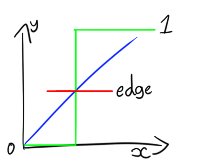
The step function quite literally will return a value of only 0 or 1 depending on a threshold, it can be recreated as so:
// identical to step(edge, x);
float MyStep(float edge, float x)
{
    if(x < edge)
    {
        return 0.0f;
    }
    else
    {
        return 1.0f;
    }
}
Now since we know what step is, we can use this to create a solid circle, if we just have our distance under a specific threshold we can color everything black, otherwise we can color everything white(or the other way around). So lets try it!
If we head back to our circle function and add a step, what will happen?
// Our circle mask maker
float Circle(vec2 uv, vec2 circleCenter, float circleRadius)
{
    return step(0.3, distance(uv, circleCenter));
}
We’re nearly there! We just have one more parameter we need to deal with which is our circle radius. Now there’s a few ways we can deal with this, the simplest way is to just to use the circleRaidus as the edge parameter in step and that does work!
// Our circle mask maker
float Circle(vec2 uv, vec2 circleCenter, float circleRadius)
{
    return step(circleRadius, distance(uv, circleCenter));
}
However I want to demonstrate another way to get you thinking about different ways to approach the same problem.
// Our circle mask maker
float Circle(vec2 uv, vec2 circleCenter, float circleRadius)
{
    return step(0.0f, distance(uv, circleCenter) - circleRadius);
}
This code above produces the exact same result, the difference is that we’re using the step function to check if a value is negative or not instead. If our pixel is in the center of the circle, it will return a distance of 0, if we take that distance of 0 and subtract our radius, our new value will be 0 - radius which is less than zero.
Our current code looks like this
// Our circle mask maker
float Circle(vec2 uv, vec2 circleCenter, float circleRadius)
{
    return step(0.0, distance(uv, circleCenter) - circleRadius);
}

void mainImage( out vec4 fragColor, in vec2 fragCoord )
{
    // Normalized pixel coordinates (from 0 to 1)
    vec2 uv = fragCoord/iResolution.xy;

    // Our output color
    float col = Circle(uv, vec2(0.5f, 0.5f), 0.1f);

    // Write the pixel
    fragColor = vec4(vec3(col),1.0);
}
Bonus, playing with the masks!
Now that we’ve created our first mask, lets play around with it and see what we can do. I’m going to reorganize the code a little so it now looks like:
// Our circle mask maker
float Circle(vec2 uv, vec2 circleCenter, float circleRadius)
{
    return step(0.0, distance(uv, circleCenter) - circleRadius);
}

void mainImage( out vec4 fragColor, in vec2 fragCoord )
{
    // Normalized pixel coordinates (from 0 to 1)
    vec2 uv = fragCoord/iResolution.xy;

    // Our output color
    float col = 0.0f;

    // Our first circle
    float circle1 = Circle(uv, vec2(0.5f, 0.5f), 0.1f);

    // Make our circle white and the background black, essentially invert it
    circle1 = 1.0f - circle1;

    // Add circles to our color
    col += circle1;

    // Write the pixel
    fragColor = vec4(vec3(col),1.0);
}
We have a white circle? So what, well now we can make more circles around just by adding to our image, so lets try it! Lets make a circle just above our current circle and make it overlap a little bit. We can do that with the code below
// Create our second circle slightly above our first and invert it as well!
float circle2 = Circle(uv, vec2(0.5f, 0.6f), 0.1f);
circle2 = 1.0f - circle2;

// Add our circle
col += circle2;
Our code should now look like this with our output as shown:
// Our circle mask maker
float Circle(vec2 uv, vec2 circleCenter, float circleRadius)
{
    return step(0.0, distance(uv, circleCenter) - circleRadius);
}

void mainImage( out vec4 fragColor, in vec2 fragCoord )
{
    // Normalized pixel coordinates (from 0 to 1)
    vec2 uv = fragCoord/iResolution.xy;

    // Our output color
    float col = 0.0f;

    // Our first circle at the center of our screen and have it's color inverted
    float circle1 = Circle(uv, vec2(0.5f, 0.5f), 0.1f);
    circle1 = 1.0f - circle1;

    // Create our second circle and invert the color. Make sure our circle is slightly above our first
    float circle2 = Circle(uv, vec2(0.5f, 0.6f), 0.1f);
    circle2 = 1.0f - circle2;

    // Add circles to our color
    col += circle1;
    col += circle2;

    // Write the pixel
    fragColor = vec4(vec3(col),1.0);
}
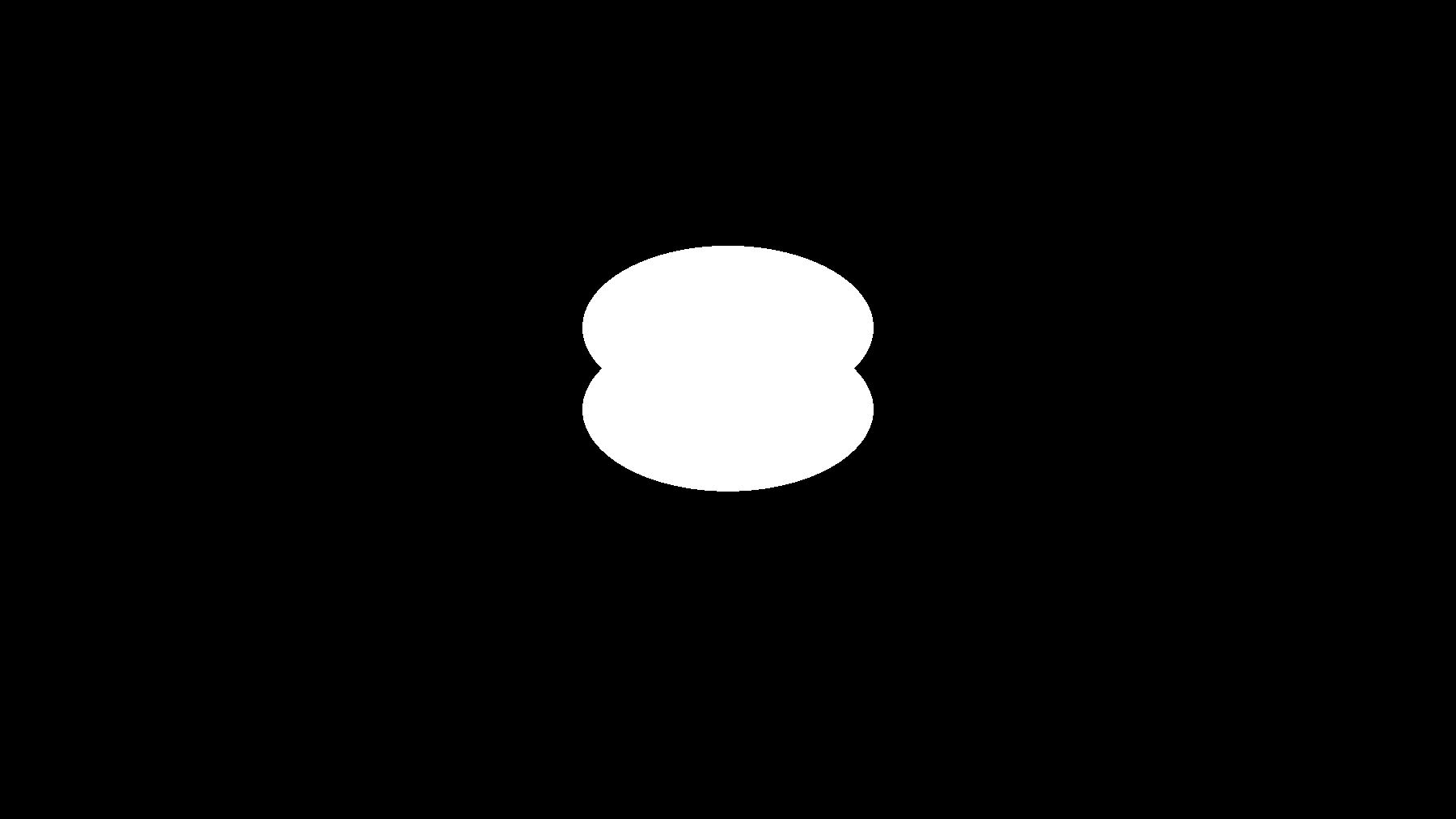
Wow check that out, we have two circles! It has an interesting shape to it but we can go further. If you ever used an image application you might of heard of “blending modes”. It’s essentially how two layers interact with each other.
col += circle1;
col += circle2;
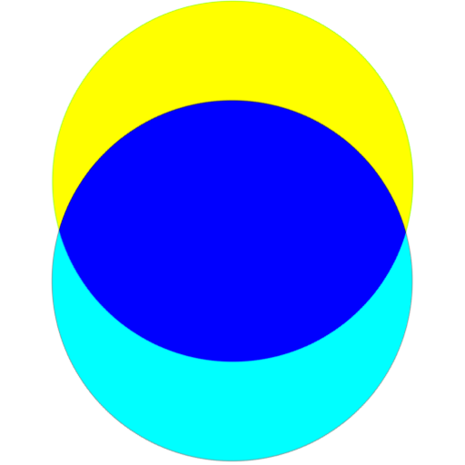
This operation here is identical to the “Add Blending Mode” seen in image applications. You take a color and add it to another color. What is happening is identical to this image below:
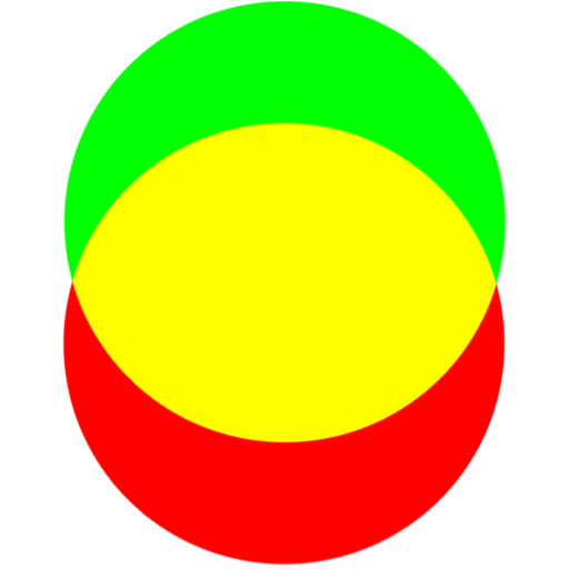
Wherever the green and red values overlap, they’re added together to create yellow. This does pose a problem as it does mean our values can be less than zero or greater than one. However we can easily clamp the values or “saturate” them. Essentially similar to step except keeping everything into the 0->1 range. GLSL does not have a saturate function but we can create our own function for it
// Identical to the saturate function in HLSL
float saturate(x)
{
    return clamp(x, 0.0f, 1.0f);
}

void Example()
{
    saturate(2); // returns 1
    saturate(1); // returns 1
    saturate(0.5f); // returns 0.5
    saturate(0); // returns 0
    saturate(-100); // returns 0
    saturate(100); // returns 1
}
However lets look at another blending mode, subtraction. It’s identical to how the add blending mode works except it takes color away, an example of it can be viewed here:
It can be implemented as simple as \(a - b\). So lets try it! We’ll go to our code
col += circle1;
col += circle2;
And we’ll change it to
col += circle1 - circle2;
And just like that we can create a super simple moon shape. We just used two different masks to make a completely new mask!

// Our circle mask maker
float Circle(vec2 uv, vec2 circleCenter, float circleRadius)
{
    return step(0.0, distance(uv, circleCenter) - circleRadius);
}

void mainImage( out vec4 fragColor, in vec2 fragCoord )
{
    // Normalized pixel coordinates (from 0 to 1)
    vec2 uv = fragCoord/iResolution.xy;

    // Our output color
    float col = 0.0f;

    // Our first circle at the center of our screen and have it's color inverted
    float circle1 = Circle(uv, vec2(0.5f, 0.5f), 0.1f);
    circle1 = 1.0f - circle1;

    // Create our second circle and invert the color. Make sure our circle is slightly above our first
    float circle2 = Circle(uv, vec2(0.5f, 0.6f), 0.1f);
    circle2 = 1.0f - circle2;

    // Add circles to our color
    col += circle1 - circle2;

    // Write the pixel
    fragColor = vec4(vec3(col),1.0);
}
Finishing words
This is just an intro into signed distance fields and how a basic shape can be turned into different shapes depending on how things are added or cut from it. This might of been a little more dense than the getting started but masks are an important topic and a lot can be done with them if you learn to master them.