Journey into fragment shaders - 1 Starting out
It’s time to demystify the magical world of shaders and time to learn about the secrets behind them! We’re going to look at the process of what a fragment/pixel shader is, how it works and how the heck we make things with it. Lets begin with some terminology on why it’s called what is it.
What’s a fragment/pixel shader
You might have noticed that I use pixel and fragment shader interchangeable. These are in-fact the same “program”. In todays world there is different rendering apis such as DirectX, OpenGL, Vulkan and Metal just to list a few. Each one of these rendering apis have different decisions on what things should be named, two of the more popular APIs use the name Fragment shader(OpenGL) & Pixel Shader(DirectX). Albeit different names, these are both the same shader program.
Why do I keep saying “shader program” instead of shader? That’s because shaders are actually small programs which run on the GPU. When you build a shader, much like a regular exe file, it’s converted into bytecode/assembly and sent to the GPU. This is all abstracted away and it’s something we never have to worry about. The only thing to note is that it IS a program which runs on the GPU.
Now lets get into the actual explanation on what fragment/pixel shaders are! When we want to draw an object on our CPU, it goes through multiple processes. We send some data to the CPU which could be our vertex and face data, we then process that data to transform it to a specific position on our screen, we optionally can do more operations such as generate extra geometry or tesselate the geometry and after all that we finally decide how to color our object in. A pixel/fragment shader dictates how we’re going to color our object in. It runs on every “sample” or “pixel” which covers the object.

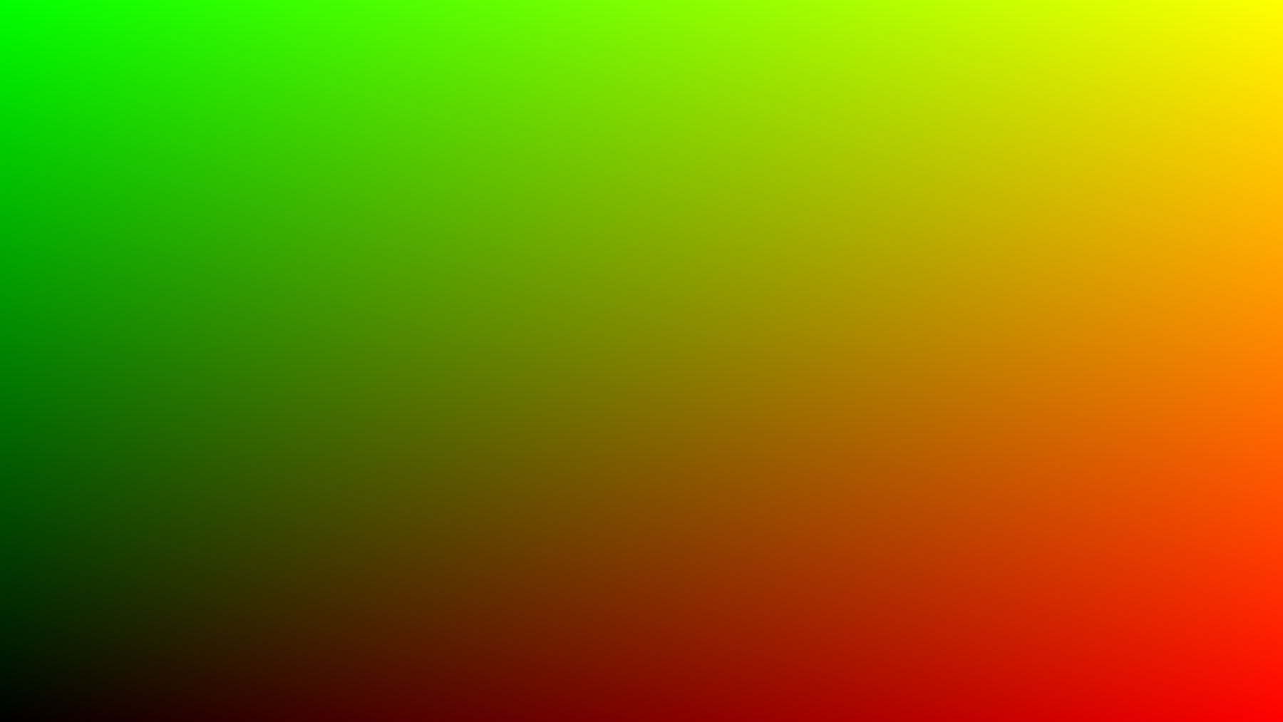
In the above image, the grid represents the screen pixels. The red represents our input and the purple represents what the fragment shader is, it’s what is ran.
So why is this difficult
In principle shaders are very very simple, however it starts to get difficult when the way shaders work are not the same as a regular computer application. Why does a GPU need to do this work and not a CPU? This is where the magic comes in! A GPU works by running your small program on ALL OF THE SAMPLES OF YOUR OBJECT AT ONCE. That’s right! If your object is covering your entire screen of 1920x1080 pixels which is 2,073,600 pixels, it’s running 2,073,600 instances your fragment/pixel all at the exact same time(not really that many all at the same time but it’s a lot)! Think about your CPU multi-threading on steroids! Due to the way this works it’s very confusing to think about how to make anything since we can’t really rely too much on the state of neighboring pixels that much. This is where we’re going to learn all ths sweet tricks of shaders! So lets begin!
Our first shader
So to create our very first shader and to get everyone started, we’ll start off with something known as GLSL which stands for The OpenGL Shading Language. The reason i’m deciding to start off with GLSL is because you can experiment right inside your browser and make shaders without needing to download or set anything special up. In the future I might showcase a bit of HLSL which is what platforms like Unity and Source 2 use. However transitioning between HLSL and GLSL isn’t too different as both shading languages share a very very similar syntax and function names.
Now as minimal as possible we’re going to go for Shader toy Shader toy is a website which allows you to create OpenGL shaders right in your browser, compile them and view them in real time! When you first create your shader you’ll be greeted with this example shader
void mainImage( out vec4 fragColor, in vec2 fragCoord )
{
    // Normalized pixel coordinates (from 0 to 1)
    vec2 uv = fragCoord/iResolution.xy;

    // Time varying pixel color
    vec3 col = 0.5 + 0.5*cos(iTime+uv.xyx+vec3(0,2,4));

    // Output to screen
    fragColor = vec4(col,1.0);
}
We have quite a bit going on here so lets trim it down make an even basic shader to start off with.
The shader we’re going to start off with is:
void mainImage( out vec4 fragColor, in vec2 fragCoord )
{
    // Normalized pixel coordinates (from 0 to 1)
    vec2 uv = fragCoord/iResolution.xy;

    // Our output color
    vec3 col = vec3(0);

    // Write the pixel
    fragColor = vec4(col,1.0);
}

We’re going to step through our shader one line at a time and figure out what’s happening and why we have a black screen, lets begin dissecting!
Understanding the basic shader
Like regular applications, shaders need to have an entry point. With HLSL/DirectX this is usually defined when we’re compiling our shader, however in the instance of using shadertoy, our entry point is always mainImage. We define our entry point as follows:
void mainImage( out vec4 fragColor, in vec2 fragCoord )
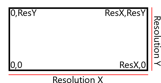
As you can see we have two arguments, one argument is an output and the other is an input from our “vertex shader”. In this context, fragColor is also known as “Fragment Color” which is what our specific pixel color is, whatever we set this variable to is what our color is going to be. fragCoord is known as our “Fragment Coordinate”, in this instance it’s the current x, y position of the pixel on the screen, where 0, 0 is the bottom left side of your screen and WIDTH, HEIGHT is the top right side of the screen.
Currently fragCoord looks like this for any given pixel on the screen if the bottom left pixel is being drawn, the program will have vec2(0, 0); as it’s value, if it’s in the middle of the screen it will be vec(ResX / 2.0f, ResY / 2.0f);
Our next shader line is
// Normalized pixel coordinates (from 0 to 1)
vec2 uv = fragCoord/iResolution.xy;
It brings up a new variable name known as a UV. That brings us to our next point:
What the heck is a UV(W)
UVs or UVWs are much like an coordinate system like how you might already know, the cartesian coordinate system with X, Y, Z and W if you’re feeling fancy. UVWs represent the same concept except it’s a coordinate which falls onto a surface like a texture. U, V and W represent the direction across the space much like how X, Y, Z represents a direction within 3D space. Now you might be thinking, how can an image have three directions? Well today is your lucky day because images can have more than two dimensions in them. This is where 3D textures come in and can exist! However this is for another time as it’s a much more advanced topic. The important take away of UVW coordinates is that it’s a coordinate system used mainly for texturing and is usually within the space of 0->1(however it doesn’t have to be!)
Back to our shader code
Now what does this actually do?
// Normalized pixel coordinates (from 0 to 1)
vec2 uv = fragCoord/iResolution.xy;
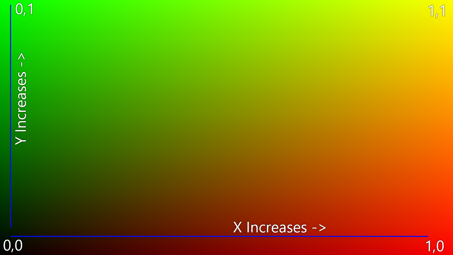
To put it simply, we’re converting the current pixel we’re drawing to map to a 0->1 range instead of 0->Resolution range. In turn we’re setting everything up to be like this:

In turn we’re “normalizing” our pixel position much like how we’d normalize a vector to become a unit vector or a directional vector.
Now for our next line we’re going to be looking at:
// Our output color
vec3 col = vec3(0); // same as vec3 col = vec3(0, 0, 0);
This line simply defines a new variable of type vec3 and zeros out all of the values. A vec3 type is the same as having 3 floats together(float3 in HLSL). vecs in OpenGL or floats in HLSL have a property known as “swizzling”. Swizzling is a special property of these types which let you assign to the variable or fetch data from the variable in a unique way.
// Examples of swizzling
vec3 variable1 = vec3(1, 2, 3);
vec3 variable2 = vec3(4, 5, 6);

// Same as vec4 variable3 = vec4(0, 0, 0, 0);
vec4 variable3 = vec4(0);

// Same as variable1 = vec3(variable2.y, variable2.z, variable1.z);
variable1.xy = variable2.yz;

// Same as variable1 = vec3(variable2.x, variable2.x, variable2.x);
variable1 = variable2.xxx;

// Same as variable1 = vec3(variable2.z, variable2.x, variable2.y);
variable1 = variable2.zxy;

// Same as variable3 = vec4(variable1.x, variable1.y, variable1.z, 1);
variable3 = vec4(variable1, 1);

// Same as variable3 = vec4(variable1.x, variable1.y, 0, 1);
variable3 = vec4(variable1.xy, 0, 1);
To put it simply, we’re just defining a basic variable.
Now lets finish out our explanation for our starter shader with:
Our final line on our basic shader is
// Write the pixel
fragColor = vec4(col,1.0);
To put it simply we’re setting our col color variable to the pixel color we want it to be with an alpha of “255”. Hang on though, our alpha says 1.0. Within shaders, all the color ranges are from 0.0 -> 1.0. That means a value of 1.0 is full intensity and a value of 0.0 is no color at all and 0.5 in in the middle.
// Full red
fragColor = vec4(1, 0, 0, 1);

// Full blue
fragColor = vec4(0.0, 1.0, 0.0, 1.0);

// Full green
fragColor = vec4(0.0f, 0.0f, 1.0f, 1.0f);
Our first “real” shader
Lets finish off with making our first real shader to demonstrate the principles of how a shader works on the GPU and why it works. We’re going to visualize the position of every single pixel in our viewport. In other words we’re going to look at our “UV” coordinates which go from 0->1. We can do this by adding
col.xy = uv.xy;
right under our color variable. If you remember from before, fragCoord returns the current pixel position and we turn that position into a 0->1 range to get our “UV”. Once you compile that shader(by pressing the Play button) you should see our UV coordinates visualized on the screen!
As our X pixel position increases, we add more red to our image, as our Y pixel position increases, we add more green into our image. If you look at our diagram before on our UV coordinates you can see this principle in action:
Final words
This is meant to just be an absolute first look into shaders, i’m planning to further expand this to teach newer concepts on how things work and slowly start introducing more and more complicated terminology for those who are interested. This is mainly a trial run to see how things go :)
Source code
void mainImage( out vec4 fragColor, in vec2 fragCoord )
{
    // Normalized pixel coordinates (from 0 to 1)
    vec2 uv = fragCoord/iResolution.xy;

    // Our output color
    vec3 col = vec3(0);

    // Visualize our UV coordinates
    col.xy = uv.xy;

    // Write the pixel
    fragColor = vec4(col,1.0);
}